- 您现在的位置:买卖IC网 > Sheet目录2005 > LTC2262CUJ-14#TRPBF (Linear Technology)IC ADC 14BIT 150MSPS 40-QFN
15
226214fc
LTC2262-14
For more information www.linear.com/LTC2262-14
APPLICATIONS INFORMATION
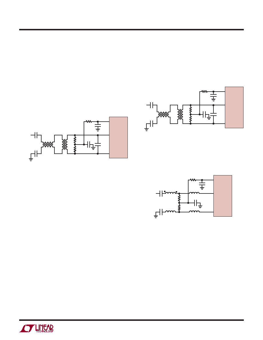
Figure 5. Recommended Front-End Circuit for
Input Frequencies from 170MHz to 270MHz
Figure 6. Recommended Front-End Circuit for
Input Frequencies Above 270MHz
DC level. At higher input frequencies a transmission line
balun transformer (Figures 4 to 6) has better balance,
resulting in lower A/D distortion.
Amplifier Circuits
Figure 7 shows the analog input being driven by a high
speeddifferentialamplifier.TheoutputoftheamplifierisAC
coupledtotheA/Dsotheamplifier’soutputcommonmode
voltage can be optimally set to minimize distortion.
Figure 4. Recommended Front-End Circuit for
Input Frequencies from 70MHz to 170MHz
At very high frequencies an RF gain block will often have
lower distortion than a differential amplifier. If the gain
blockissingle-ended,thenatransformercircuit(Figures 4
to 6) should convert the signal to differential before driv-
ing the A/D.
25
50
0.1F
AIN+
AIN–
4.7pF
0.1F
VCM
ANALOG
INPUT
0.1F
T1
T2
T1: MA/COM MABA-007159-000000
T2: MA/COM MABAES0060
RESISTORS, CAPACITORS ARE 0402 PACKAGE SIZE
226214 F04
LTC2262-14
25
50
0.1F
AIN+
AIN–
1.8pF
0.1F
VCM
ANALOG
INPUT
0.1F
T1
T2
T1: MA/COM MABA-007159-000000
T2: COILCRAFT WBC1-1LB
RESISTORS, CAPACITORS ARE 0402 PACKAGE SIZE
226214 F05
LTC2262-14
25
50
0.1F
2.7nH
AIN+
AIN–
0.1F
VCM
ANALOG
INPUT
0.1F
T1
T1: MA/COM ETC1-1-13
RESISTORS, CAPACITORS
ARE 0402 PACKAGE SIZE
226214 F06
LTC2262-14
发布紧急采购,3分钟左右您将得到回复。
相关PDF资料
LTC2262IUJ-12#PBF
IC ADC 12BIT 150MSPS 40-QFN
LTC2264CUJ-12#PBF
IC ADC 12BIT SER/PAR 40M 40-QFN
LTC2268IUJ-14#TRPBF
IC ADC 14BIT 125MSPS DUAL 40QFN
LTC2280CUP#PBF
IC ADC DUAL 10BIT 105MSPS 64-QFN
LTC2281IUP#PBF
IC ADC 10BIT DUAL 64-QFN
LTC2282CUP#PBF
IC ADC DUAL 12BIT 105MSPS 64-QFN
LTC2284CUP#PBF
IC ADC DUAL 14BIT 105MSPS 64-QFN
LTC2285CUP#PBF
IC ADC DUAL 14BIT 125MSPS 64QFN
相关代理商/技术参数
LTC2262IUJ-12#PBF
功能描述:IC ADC 12BIT 150MSPS 40-QFN RoHS:是 类别:集成电路 (IC) >> 数据采集 - 模数转换器 系列:- 标准包装:1 系列:- 位数:14 采样率(每秒):83k 数据接口:串行,并联 转换器数目:1 功率耗散(最大):95mW 电压电源:双 ± 工作温度:0°C ~ 70°C 安装类型:通孔 封装/外壳:28-DIP(0.600",15.24mm) 供应商设备封装:28-PDIP 包装:管件 输入数目和类型:1 个单端,双极
LTC2262IUJ-12#TRPBF
功能描述:IC ADC 12BIT 150MSPS 40-QFN RoHS:是 类别:集成电路 (IC) >> 数据采集 - 模数转换器 系列:- 标准包装:1 系列:- 位数:14 采样率(每秒):83k 数据接口:串行,并联 转换器数目:1 功率耗散(最大):95mW 电压电源:双 ± 工作温度:0°C ~ 70°C 安装类型:通孔 封装/外壳:28-DIP(0.600",15.24mm) 供应商设备封装:28-PDIP 包装:管件 输入数目和类型:1 个单端,双极
LTC2262IUJ-14#PBF
制造商:Linear Technology 功能描述:ADC Single Pipelined 150Msps 14-bit Parallel/LVDS 40-Pin QFN EP 制造商:Linear Technology 功能描述:IC ADC 14BIT 1.8V 150MSPS 40-QFN
LTC2262IUJ-14#TRPBF
制造商:Linear Technology 功能描述:ADC Single Pipelined 150Msps 14-bit Parallel/LVDS 40-Pin QFN EP T/R 制造商:Linear Technology 功能描述:IC ADC 14BIT 150MSPS 40-QFN
LTC2263-12
制造商:LINER 制造商全称:Linear Technology 功能描述:12-Bit, 65Msps/40Msps/25Msps Low Power Dual ADCs
LTC2263-14
制造商:LINER 制造商全称:Linear Technology 功能描述:Quad 14-Bit, 125Msps ADC with Integrated Drivers
LTC2263CUJ-12#PBF
功能描述:IC ADC 12BIT SER/PAR 25M 40-QFN RoHS:是 类别:集成电路 (IC) >> 数据采集 - 模数转换器 系列:- 标准包装:1 系列:microPOWER™ 位数:8 采样率(每秒):1M 数据接口:串行,SPI? 转换器数目:1 功率耗散(最大):- 电压电源:模拟和数字 工作温度:-40°C ~ 125°C 安装类型:表面贴装 封装/外壳:24-VFQFN 裸露焊盘 供应商设备封装:24-VQFN 裸露焊盘(4x4) 包装:Digi-Reel® 输入数目和类型:8 个单端,单极 产品目录页面:892 (CN2011-ZH PDF) 其它名称:296-25851-6
LTC2263CUJ-12#PBF
制造商:Linear Technology 功能描述:IC ADC 12BIT 25MSPS QFN-40